I recently got a request to add bidirectional transceivers to my SDI-12 USB adapters to handle very long SDI-12 bus wires (result of long wires for each sensor and a large number of sensors). Currently a couple of these adapters are being tested by one customer who requested this feature but I am pretty confident with its functions and will conduct my own testing with long wires. If this is what you have in mind, I have a handful of them I’ve built as prototypes. You can go ahead and purchase a regular SDI-12 USB adapter and request one with a transceiver. I don’t have a lot of them so I can only send you one or two. If you really need more of these, I’ll need to order boards and components.

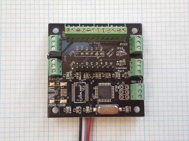
The added transceiver will not affect any program code such as my Python data logging script. It is operated transparently. When the adapter receives a complete SDI-12 command, it will turn on the transceiver and transmit the command to the SDI-12 bus. Once done with transmission, it turns the transceiver off and returns to listening mode. The transceiver in the following photo is located just to the left of the top-right 3-pole terminal block (small black rectangle with 6 pins).
Additionally, I have received several requests to use my USB adapter as a TTL/serial adapter, such as connecting to arduino or MicroPython boards, either at 5V or 3.3V. I’ve updated my board design to make those requests easier to fulfill. This option is now added to inmojo marketplace as well as to Tindie marketplace (options used to cost $2.5 and now is free).
First, if you purchase a TTL/serial only adapter, you will not get USB connection anymore (notice the missing long black chip to the right of the empty USB connector pattern). You can’t really have both active simultaneously since there is only one TTL/serial port on the processor. It’s either connected to the breakout pins for TTL/serial use, or connected to the USB chip to communicate to PC/raspberry pi. The use cases of USB vs. TTL/serial also don’t overlap. One is for those who want to use PC or raspberry pi to log data, and another who want to use MicroPython boards or Arduino boards to log data. What you will get is a 6-pin connector on the bottom of the board, at 90 degrees so it’s not pointing straight down, rather sideways. See how the wires are under the board, running along the board and the next photo for the underside. This makes it possible to stack expansion boards or have optional analog/digital input headers (12-pole block on top edge). You still need a 5V supply even if you want a 3.3V TTL/serial interface. The following photo shows a 3.3V version. Note the solder blob on the top right to the immediate left of the text “TX3”. Then the TX3 on the serial port (marked JP9 on left and Serial Port on right) is outputting 3.3V logic. Remember that the adapter’s TX or TX3 should be connected to your other board’s RX pin since the adapter’s transmit (T) goes to your other board’s receive (R).