It may be just me but I am interested in reading code written by others. It’s like literature. Everyone has a different style and you can always pick up something useful if you read. But some beginners read code written by others simply because they wanted to use that code on their own projects. If you have already done that as a beginner, you may have seen what I am about to introduce: the #define.
These “#define” appear in the beginning of some project code and you may wonder what they do and why they are there. Here is some light reading about the “#define”:
First of all, the #define is not declaring or defining a variable. It is simply a substitution rule.
Example:
#define foo bar
If you have the above at the beginning of your code, then every time foo shows up in subsequent code, it gets replaced by bar. Normally only complete match is replaced so foobar won’t be replaced by barbar. Also foo inside a text string is not replaced either.
This “#define” command is called a preprocessor directive. The substitution occurs before the code is compiled, thus the name.
There are a lot of good use for this directive. If you want to blink an LED, you can do:
But that would suck if you want to blink a different pin. You have to change pin number in multiple lines and pray not to make a mistake. But this will work much better.
#define LED 13
digitalWrite(LED,HIGH);
delay(1000);
digitalWrite(LED,LOW);
delay(1000);
This way if you move the LED to pin 10, all you have to do is to modify the “#define LED 13” into “#define LED 10”. Obviously in this example the first way only requires two changes to blink LED on pin 10. On the other hand, if you have programmed the game Angry Bird with earth gravity g=9.81m/s/s and suddenly want to expand your game to moon, where gravity g=1.62m/s/s, good luck to you if you typed in 9.81. There would be thousands of places where 9.81 was typed in and need to be changed. And from reading the program, you will have no idea what gravity value was used (just seeing a 9.81 in a calculation doesn’t count as knowing gravity is 9.81). Now if you did “#define g 9.81” in the beginning of your code, remaking your Angry Bird on the moon will only take two seconds on your coding and it will also be obvious to the reader of your code, which is probably 90% chance yourself at a later time. You will be surprised how forgetful you are.
There are a lot of advanced uses of “#define” to control how your code gets compiled, which in my opinion is not useful for beginners. I will cover that in a separate post. Just as a teaser, let’s think about this question: you have two prototypes, prototype1 with a 16X2 LCD and 4X4 matrix keypad, prototype2 with a 20X4 LCD and rotary encoder. Your project code works on both hardware but the initialization part is dependent on which prototype you are using. You will be able to use something like “#define prototype1” to make the compiler only compile initialization code for prototype1. Just exactly how, I will cover it in a separate post.
This is a basic skill for anyone trying to tinker with electronics yet everyone starting off can use some general guidance on how to use a breadboard.
A breadboard, or a solderless breadboard, is a platform where you lay out your circuit, similar to a piece of paper where you can draw the circuit. You will be able to put components down on the breadboard and interconnect them to form your circuit. It’s important to first draw up a connection diagram on a piece of paper so you can use it as guide to connect up components on your breadboard, especially for complex circuits, or you are just starting with electronics.
How does a breadboard work?
So how does a breadboard work? Simple. If you draw up a circuit, you notice these junctions that connect up several wire ends, right? If you build this circuit, you will use something to hold these wire ends, possibly with a metal paper clip so you get good contact and they don’t fall apart, right? That’s exactly how a breadboard works. There are tiny metal clips that can hold on to your wires so you can make these junctions. Each clip has 5 holes above it so you can connect up to 5 wire ends by inserting them into these 5 holes. Take a look at the following pictures:
On the first picture you will see a miniature breadboard. It has a groove in the middle, separating its two halves. You will notice each half has 5 columns of holes. Take at a look the back side of the breadboard on the next image in the gallery. I removed the protective backing and walla! You can see these metal clips behind the holes. Each clip is behind a row of 5 holes. See the third picture. So now you know that each row of holes should represent a junction that can connect up to 5 wire ends, using the metal clip below these holes. In the fourth picture I was holding one clip in my hand. You can see the clip is cut into 5 sets of separate prongs. This allows the clip to grab on to 5 wire ends of different diameters and have good grip on them all instead of only holding the thickest wire and letting loose the rest.
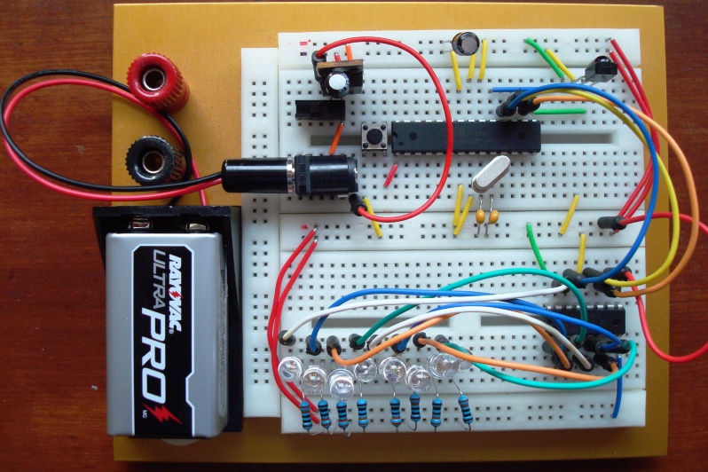
Now that you know how a breadboard works, it’s time to learn how to use a breadboard. Before moving on, take a look at the last image. It’s a project I built on a breadboard. There are 8 individual LEDs that will light up and flash different patterns and programmable all via a remote control. Pretty fancy?
Enjoy a video before moving on so you know if you can use a breadboard, you can do something just as fancy:
How to use a breadboard?
To use a breadboard, you first need a circuit to build on it. Let’s build something useful. In this previous post, I described how to use a thermistor to measure temperature:
This is a voltage divider. You have a known resistor (10Kohm), and an unknown resistor (the thermistor, which changes resistance with temperature). You also have 5V and ground, besides an analog sensing pin from Arduino.
To build this circuit on a breadboard, we realize that there are 3 junctions:
The junction above R_known, with 5V and R_known coming together
The junction between R_known and R_unknown, with both resistors and arduino pin coming together
The junction between R_unknown and GND, with R_unknown and GND coming together
To build the circuit, we need to use three rows of holes to do these three junctions. Here is the finished circuit:
Well, you noticed the image of the finished circuit is not an actual breadboard. To be honest, I don’t have a breadboard at my desk and photographing real breadboards often gives you the wrong perception of which wire goes to which header due to the different depth between the jumper wire end and the header. I have helped enough people with their circuit by viewing their breadboard photos. This common problem is seen on nearly every overhead photo. Another nice thing about this photo generated in Fritzing is that the rows of 5 holes are highlighted with green so you know these 5 holes are interconnected. They even do the resistor color coding right.
If you have a regular power supply, such as a student +-25V power supply, you should wire the power from the power supply to the banana sockets on a full-size breadboard and wire the power from there to the power buses, which are the columns on the outside with red and blue lines. All the holes along the same red line are connected. Different red columns are not connected. Once you have these convenient buses, you can just derive power from the buses instead of wiring multiple wires from the power supply. Take a look at the following images for a more complete understanding of what are connected together and how the power buses are used in an actual circuit:
Now you probably noticed that there is an integrated circuit (IC) in that last picture. Take another look at it just to remember how it is put onto the breadboard. Aha! That’s why there are these grooves! With an IC, you put it on the breadboard so that it sits right above the groove. This way you will have access to all its pins instead of shorting their pins if you push it onto the rows of 5 connected pins.
For more complicated circuits, you will need to plan ahead on how to lay it on the breadboard, try to spread out instead of squeezing at a corner.
Now take a look at this picture again just to have a better understanding on how the breadboard is used and you’re ready for the road!
A little while ago the store owner of dipmicro.com approached me regarding their kits sales. He has decided to discontinue selling any or all kits, including the phi-2 shields they have been carrying for the past few years. At the moment all kits that were sold there are gone. Only those designed by dipmicro are still selling. Instead of selling kits, he thought it would be better for him to sell assembled products. It is unfortunate that I lost a vendor but I still keep them on my list of parts suppliers. Maybe in the future when I will be selling fully assembled arduino gadgets I will ask them to carry again.
I got a request from Kenny G. that he wants to run OLED displays on phi-panels and got interested in modifying the software and hardware to work. Thanks to Kenny, who loaned me an OLED display from adafruit (wintech 1602AB), I was able to tinker with it last night and today. I eventually made it to work:
Here is some photos:
One of the photos is a diagram on how to modify the backpack PCB. Please check out the google code page regarding the firmware.
Pretty bad, basically clear() blink() cursor() display() and their counterparts are not working. I confirmed most of these with the simplest setup. On the other hand, home() works so I can limp on with home() and writing a lot of blanks to clear but can’t show cursor or blink anymore.
So I commented out these functions and modified clear() to write 80 spaces and do a home(). It works as it should. With other software this would have flicker on the screen but with phi-panel’s display buffer, it does not flicker.
In the future, if there is enough interest, I will make some special backpack PCBs that don’t need modification to work with OLEDs.
Meanwhile Kenny is testing other OLEDs he has regarding adafruit library usability. I felt that adafruit didn’t go all the way to provide a reliable library for us this time but without spec sheet, what more than this can they do? Maybe being a bit more upfront with their limitations?!
Happy New Year everyone! Thank you for the over 100,000 visits and countless comments. I am hoping with the new year, I can make more basic tutorials so this site will be helpful for both newbies and those that are interested in the family of phi hardware and software.