How to use a breadboard
January 15, 2013 Leave a comment
Introduction:
This is a basic skill for anyone trying to tinker with electronics yet everyone starting off can use some general guidance on how to use a breadboard.
A breadboard, or a solderless breadboard, is a platform where you lay out your circuit, similar to a piece of paper where you can draw the circuit. You will be able to put components down on the breadboard and interconnect them to form your circuit. It’s important to first draw up a connection diagram on a piece of paper so you can use it as guide to connect up components on your breadboard, especially for complex circuits, or you are just starting with electronics.
How does a breadboard work?
So how does a breadboard work? Simple. If you draw up a circuit, you notice these junctions that connect up several wire ends, right? If you build this circuit, you will use something to hold these wire ends, possibly with a metal paper clip so you get good contact and they don’t fall apart, right? That’s exactly how a breadboard works. There are tiny metal clips that can hold on to your wires so you can make these junctions. Each clip has 5 holes above it so you can connect up to 5 wire ends by inserting them into these 5 holes. Take a look at the following pictures:


On the first picture you will see a miniature breadboard. It has a groove in the middle, separating its two halves. You will notice each half has 5 columns of holes. Take at a look the back side of the breadboard on the next image in the gallery. I removed the protective backing and walla! You can see these metal clips behind the holes. Each clip is behind a row of 5 holes. See the third picture. So now you know that each row of holes should represent a junction that can connect up to 5 wire ends, using the metal clip below these holes. In the fourth picture I was holding one clip in my hand. You can see the clip is cut into 5 sets of separate prongs. This allows the clip to grab on to 5 wire ends of different diameters and have good grip on them all instead of only holding the thickest wire and letting loose the rest.
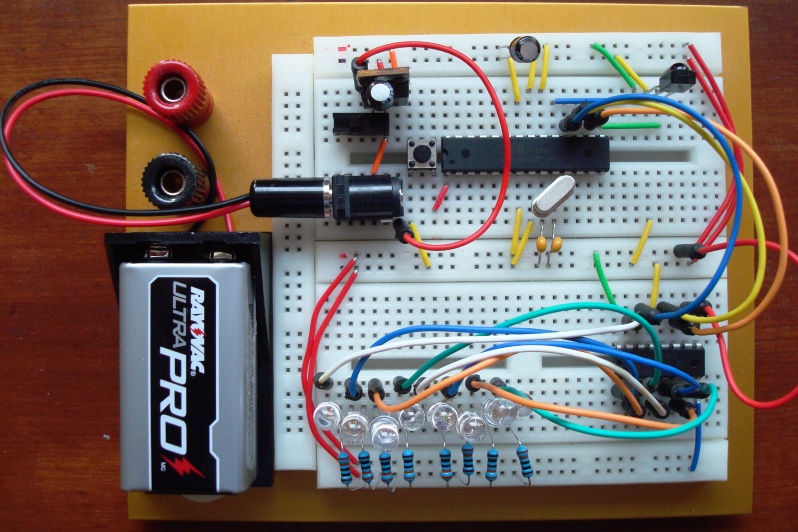
Now that you know how a breadboard works, it’s time to learn how to use a breadboard. Before moving on, take a look at the last image. It’s a project I built on a breadboard. There are 8 individual LEDs that will light up and flash different patterns and programmable all via a remote control. Pretty fancy?
Enjoy a video before moving on so you know if you can use a breadboard, you can do something just as fancy:
How to use a breadboard?
To use a breadboard, you first need a circuit to build on it. Let’s build something useful. In this previous post, I described how to use a thermistor to measure temperature:
http://liudresllc.com/2011/02/10/measure-temperature/
There is a circuit in the post:
This is a voltage divider. You have a known resistor (10Kohm), and an unknown resistor (the thermistor, which changes resistance with temperature). You also have 5V and ground, besides an analog sensing pin from Arduino.
To build this circuit on a breadboard, we realize that there are 3 junctions:
- The junction above R_known, with 5V and R_known coming together
- The junction between R_known and R_unknown, with both resistors and arduino pin coming together
- The junction between R_unknown and GND, with R_unknown and GND coming together
To build the circuit, we need to use three rows of holes to do these three junctions. Here is the finished circuit:

Well, you noticed the image of the finished circuit is not an actual breadboard. To be honest, I don’t have a breadboard at my desk and photographing real breadboards often gives you the wrong perception of which wire goes to which header due to the different depth between the jumper wire end and the header. I have helped enough people with their circuit by viewing their breadboard photos. This common problem is seen on nearly every overhead photo. Another nice thing about this photo generated in Fritzing is that the rows of 5 holes are highlighted with green so you know these 5 holes are interconnected. They even do the resistor color coding right.
If you have a regular power supply, such as a student +-25V power supply, you should wire the power from the power supply to the banana sockets on a full-size breadboard and wire the power from there to the power buses, which are the columns on the outside with red and blue lines. All the holes along the same red line are connected. Different red columns are not connected. Once you have these convenient buses, you can just derive power from the buses instead of wiring multiple wires from the power supply. Take a look at the following images for a more complete understanding of what are connected together and how the power buses are used in an actual circuit:


Now you probably noticed that there is an integrated circuit (IC) in that last picture. Take another look at it just to remember how it is put onto the breadboard. Aha! That’s why there are these grooves! With an IC, you put it on the breadboard so that it sits right above the groove. This way you will have access to all its pins instead of shorting their pins if you push it onto the rows of 5 connected pins.
For more complicated circuits, you will need to plan ahead on how to lay it on the breadboard, try to spread out instead of squeezing at a corner.
Now take a look at this picture again just to have a better understanding on how the breadboard is used and you’re ready for the road!