Phi-connect

Thank you for your support! This gadget has been discontinued. The following is only for archiving purposes.
So what is a phi-connect?
Phi-connect is a wire/cable management system for Arduino. It passes all Arduino connections to a breadboard with one cable. You can connect your Arduino to a project with just one step. Forget about reconnecting dozens of jumper wires! You can switch from one project to another project in 3 seconds. How can you do that if you used jumper wires. You will also be able to mount phi-connect inside your project box. When you need your Arduino back, unplug it. You leave $4 worth of board inside your project box and reuse the rest on a new project. Anytime you miss you old project, plugging Arduino back in takes 3 second. Once the Arduino is plugged back in, your project springs into life!
The special features of phi-connect:
- Passes all Arduino pins to the breakout board to be plugged into breadboards or soldered inside a project box.
- Two places with 5V/GND pins directly plugs into power buses to power the breadboard and improves mechanical strength.
- Two strips of connections 5V/GND helps you connect sensors and motors in your project box
- Mounting holes help you secure the board in a project box
- Mechanical key on the cable prevents mistakes when inserting the cable.
- The stackable version can be stacked below any arduino shield, benefiting from shield function and breadboard freedom with seamless connections.
Where to buy:
Please click this link to redirect to the “buy” page for where to purchase this hardware.
Pictures and videos
Here is a slide show of pictures, assembling the phi-connect and using it.
You can easily switch from one project to another without reconnect dozens of wires:

Breakout board version 1.9 (compatible with original version):

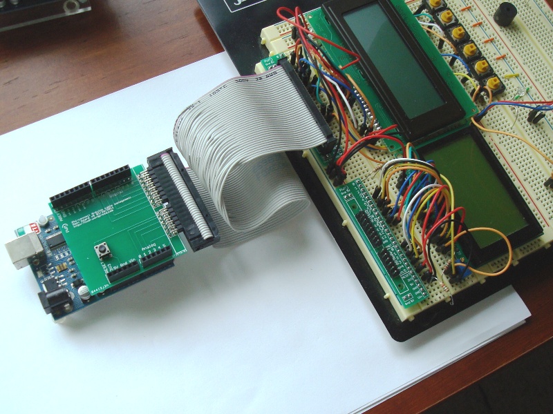
Two projects are on the breadboard, right being a sonic ranger sensor project in its infancy, left being an alarm clock project. Both have a breakout board (two thin boards on top). I can connect to either project with phi-connect.


Left image shows the dot matrix LCD is running test code for sonic ranger. Right image shows the character LCD is running alarm clock project (with two buttons). No need to reconnect jumper wires when switching between projects, no messy wires.
How to assemble the kit:
Here is an instructable on how to assemble the kit.

http://www.instructables.com/id/Arduino-tutorial-organize-your-projects/
Video of switching between two projects:
Documentation
-> Click here to download documentation version 20120329<-
-> Click here to download older version documentation version 20110424<-
Do you want to contribute pictures?
I will be more than willing to include your project pictures before and after using phi-connect in my manual if you send me some.
Please post photos of the Phi-Connect and the Phi-2 board. I love the Phi-1 shield and your well-commented code. Looking forward to Phi-2 projects.
Have an OUTSTANDING day!
Sure Patrick, will do later today. I got all the pictures and diagrams. Still combing through the documentation.
Patrick,
I’ve updated this page. Now you can see pictures and a video of how phi-connect works.
This is a really great idea. I love it. Have you considered making the design open source and publishing the design files? Like I did with my Ardunio compatible project: http://www.instructables.com/id/Make-your-own-1×1-22-IO-pin-Ardunio-Compatible/
Since I can make PCBs at home, it would be neat to be able to make it myself.
Not yet but it sound like a good idea. I will give it a consideration once I sell out what I made 😉
Great idea, Just a recomendation if you were to make a second revision of the board, would be to add a prototyping space on the shield.
I am thinking that having that many holes on the small breadboard adapter piece already upset the manufacturer (so many holes to drill). If it helps, I’ll consider moving the reset button to a corner so you can glue on a mini breadboard like this one:
https://www.sparkfun.com/products/7916?
Maybe that helps? I’m going to do my next iteration of the board revision. Let me know if this might help.