Actually, these features have been there for a while now. I didn’t mention them just to make sure that the older PCB revisions are sold out and if you’re making new purchases, you’ll get the new PCBs with these features.
One of the features is a 5-pin USB header. You already have a microUSB connector so why another USB? This is because you can more easily route cables. A microUSB connector requires a microUSB plug, which requires about 2 inches or 5cm of space beyond the board’s edge. A 5-pin female header to USB-A cable with the 5-pin male header requires zero inches or cm. This makes the board fit inside smaller enclosures or leaves more space for other devices inside the enclosure.
Have a look at the following photo for a comparison:
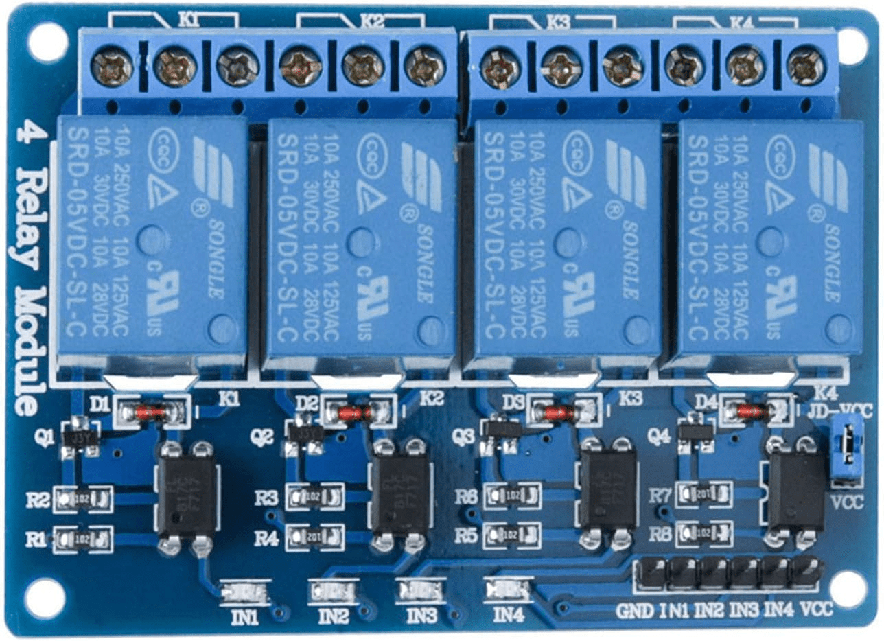
Another feature is a header near the analog/digital input terminal block header. This header is a reorganized header from the analog/digital input terminal block. It brings out 5V, channels 3,2,1,0, and GND. This header makes it easier to connect these channels to a 4-relay module to control relays like this one (header on bottom right):
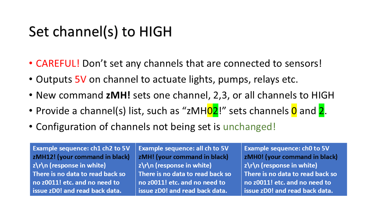
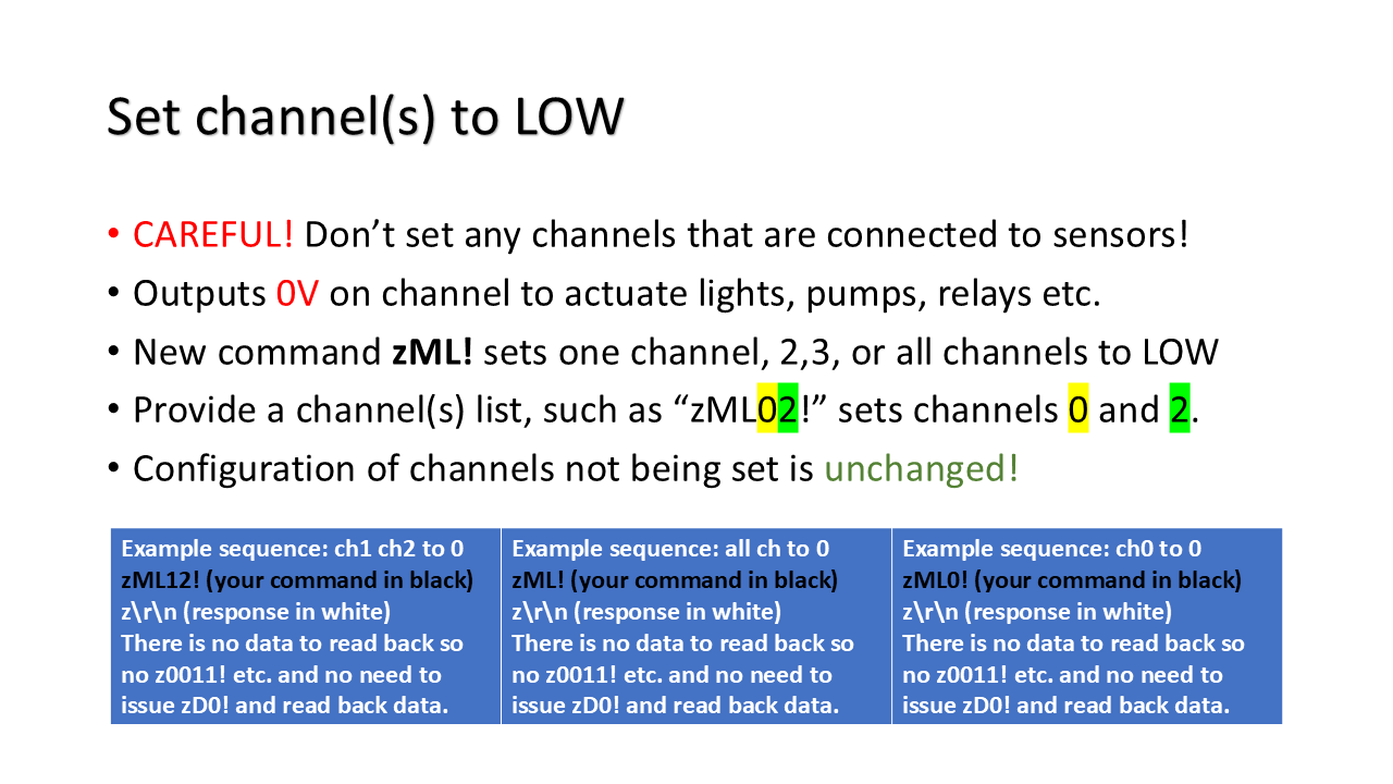
Even though these 4 channels are advertised as input channels, there are actually commands to use them as output channels! This way you can read your SDI-12 sensors and then actual relays to do irrigation or fan control all on this one board!
Recently a customer asked me whether there can be a UART interface to integrate the SK-16 adapter with an ESP32 adapter. I thought, why not? So, after some soldering, I modified a regular SK-16 USB adapter into a UART adapter. It has 5V, GND, TX at 5V, TX at 3.3V, and RX, all brought out on the expansion port.
Here is a photo of the modified adapter with an ESP32-WROVER dev board and an old Decagon soil sensor. I tested the whole thing first with a USB-UART adapter and then with the ESP32 running MicroPython.
This modification took a while so it’s ok if it’s just once in a while. But if you want a few of these, I may consider making a version of the board. Leave me some comments.
Here is a tricky thing I had to do to make this modification:
What we are looking at is a slotted screwdriver. The blade rested on a very tiny piece of wire I had to solder between the square IC and the rectangular IC. The pitch of these ICs are less than 0.05″ or about 1mm. If I went ahead to solder one side, then soldering the other side will cause the soldered side to melt and I ended up desoldering the wire because it’s so small. So I used the screw driver to both pin the wire down and provide thermal relief to the soldered side.
Here is another idea. What if I added female headers so I can just drop an ESP32 dev board on to the SK-16 board? No soldering and no wiring, great!
The above is just a mock-up. But the only problem is that there are so many ESP32 dev boards and they all have slightly different pinouts and spacing between the rows of pins. This will have to be custom-made to fit the ESP32 dev boards you use. If you are interested, leave me some comments what ESP32 boards you use. The one photographed is an official Espresiff dev board, ESP32_Devkit_V4. It has wider spacing between the two rows of pins but the pins are clearly printed next to the pins.
Every time I type a question into Google AI, I wonder if that caused a tree in the Amazon or something. AI is very hardware and resource intense to run. I read about how the skyrocketing RAM price from the AI boom is causing Apple to quietly discontinue their top-tier local-AI-running desktop with 512GB of RAM and bumped up prices for lower tier ones with 256GB and 64GB RAM. People trying to run their own AI models are scrambling to find those top-tier Macs whole some are price gouging, sometimes $10K more than the price just last year!
Here is how that apocalypse might be affecting us. Enter, 2025 vs 2026 May chart. I know that many of us use Raspberry Pi 5 computers to run data logger routines, which is fine, but the price hike has changed the overall behaviors of my customers for sure. I plotted out the price of RPI5-8GB May 25 vs May 26, a whopping $120 increase from the $80 price that I personally paid last May for a couple of them! See the blue line.
Now, also see the orange line of SDI-12 microUSB units sold, about a 50% decline! I bet that was related to the rarity and high price of RPIs! But at the same time, the miniUART module sales really took off! See the green line. From not selling much at all to overtaking microUSB units! I bet more and more customers are using microcontrollers like Arduino, or ESP32, or Raspberry Pi Pico (not Pi, Pi Pico), to make their data loggers to save cost!
So, I am inclined to use this summer to release more videos and sample code to aid the transition from microUSB adapters to miniUART modules, targeting the three most common microncontrollers, Arduino nano ESP32 with C/C++, ESP32 dev board with MicroPython, and RPI PicoW/Pico2W with MicroPython. If you think this is a good idea and it helps your, please put in some comments so I know I’m headed in the right direction.
I recently sold out all the SDI-12 miniUART modules from the last batch. I designed this module for others to easily incorporate SDI-12 into their system. With new orders coming in, I immediately made one new batch of 100 modules. Here they are:
Each panel contains 20 modules. I assembled a total of 5 panels, so 100 modules! I used a different programmer to flash the firmware onto these modules via the 3*2 header pattern. But I also needed to test these modules against an actual SDI-12 sensor. Last time I made a batch of these, I broke the modules out into single modules to test them one at a time on my regular flash-test jig. It was a bit difficult to secure. So this time I made a new tester with 6 pogo pins to connect to the 3-pin headers on the sides of the module. I don’t have to break the modules into singles and the jig was easier to use:
Because how I designed the modules, the mounting hole is on a 0.1″ pattern so I just drilled through one solder hole on the perf board and added a standoff to make alignment easier. I should have moved the pogo pins further up to possibly have space for the other mounting hole. Oh well!
At this angle, you can see the pogo pins on the right side of the board. So I just line up the standoff against the top-left mounting hole and press down to connect to the pogo pins, then let the MicroPython script running on my raspberry pi pico test SDI-12 communication.
Here is a simplified script:
fromtimeimportsleep
frommachineimportUART,Pin
uart0=UART(0,baudrate=9600,tx=Pin(0),rx=Pin(1))
i=0
while(True):
sleep(0.5)
uart0.read(uart0.any())# Flush input
uart0.write(b"?!")
sleep(0.5)
reading=uart0.read(uart0.any())
ifb'\r\n'inreading:
print(i,reading)
i+=1
What the script does is to send ?! to the sensor so the sensor will identify itself such as 1\r\n or if the module can’t talk to the sensor, it will not print anything. In addition, a number is printed before the response such as 2 1\r\n then 3 1\r\n etc. so you can tell whether the current board is responding. Just remember the last number from the last module you tested. If the new module you’re testing works, a larger number will be printed along with the response.
You can see how easy it is to start a project with my module and MicroPython. It really won’t take more than a few lines of code.
If your SDI-12 adapter isn’t “working”, don’t panic! The adapter has been tested with an actual SDI-12 sensor so it’s supposed to work. Go through the following steps to troubleshoot the adapter. As a matter of fact, DO the following step BEFORE you put any adapter to use for the first time!
1. Remove any sensors or external power connections from the adapter. Check for any physical damages on the USB port, the board, and terminals.
2. Plug the adapter into a windows computer, if the computer recognizes the adapter with a “USB plugged in” chime, and your device manager shows a serial port just appeared, proceed. Otherwise, the adapter is either damaged or the USB port may be damaged. If it shows a message saying an unrecognized device, the USB chip is damaged. The following is a screen shot of my device manager. The serial port COM15 wasn’t there before I plugged in my adapter. Opening the property of the port shows the manufacturer as FTDI (the USB chip). This confirms this step is successful.
3. While connected to PC, use putty (available in windows app store) or tera term and connect to the serial port you observe that appeared in step 2, with 9600 baud rate and 8 bit data, 1 bit start, 1 bit stop, no parity (default settings for many terminal programs), type in zI!, which is zee-EYE-! without hitting enter. If the adapter responds, then proceed. The following screen shot is the set up screen of PuTTY. Make sure you select the connection type as Serial and type in the correct serial port name and speed.
You won’t be able to see what you typed in (no local echo unless you turn on that feature) but you will see the response from the adapter as below. Your version of firmware may be different from 1.5.9 (159) though. If there is no response, the SDI-12 interface chip may have been damaged.
4. Close PuTTY connection. Disconnect the adapter from your computer. Connect a sensor that you know works (just tested to work). Reconnect the adapter to your computer and open PuTTY again. In the terminal program, issue ?! command. If the sensor responds with its address such as 1 in the following screen shot, the adapter works. You can follow up with an identification command 1I! that is 1-EYE-! and replace 1 with the address you see on screen after ?!. You may have to connect 12V to the adapter’s power input and select to use this power input with a jumper for certain sensors. Consult with your sensor’s manual for operating voltage. If there is no response from either ?! or the identification command, the SDI-12 chip may have a damaged data pin.
Before asking for some help, please test the adapter with the above procedure and tell me what you see. Try to avoid generic descriptions such as “failed” or “not working” and describe what you did and what you observe.
After some tests by Dr. Michael Santiago and myself, I can confirm that the FloraPulse stem water potential sensor is supported. One just needs a 1-second delay between SDI-12 commands. Here is a forum post:
If you have read about my SDI-12 USB adapters, you might know that besides connecting SDI-12 sensors to a USB port for PC/raspberry pi, the adapter has an option to read basic 0-5V analog voltages, digital inputs, and count pulses. This extra feature comes as a 12-pole terminal block at the top of the adapter, allowing up to 4 analog inputs, or 4 digital inputs, or 4 pulse counters:
This option has been around for a number of years but has not been widely used. Most people purchase the basic adapter without this $10 option. So is this option useful for you? That depends on what you are planning to do. Say for instance, you have an analog sensor such as a temperature and relative humidity sensor that you want to read besides SDI-12 sensors, if 5mV to 10mV accuracy is good enough for you, then you can read your analog sensor with this option. Do you have a pulse sensor such as a tipping-spoon rain gauge or a flow meter? Then the pulse counter feature would help you integrate these sensors with ease. If you have digital ON/OFF or HIGH/LOW sensors that have 0-5V or 0-3.3V logic, you can read them too.
The easiest way to acquire these sensors is to get the ADI (analog digital input) feature with your purchase. For extra $10, you will have an adapter that comes with a 12-pole terminal with all 4 inputs tested. The best part is, reading these sensors is very easy, just like reading an SDI-12 sensor. This way you can treat an analog temperature sensor just the same way as an SDI-12 sensor. Here is an introductory video:
Here is a link to my online store. To select the option, drop down the selection menu and choose “Analog and digital input header”.
After some requests from customers, I have decided to design a small module that can help everyone prototyping and embedding SDI-12 in their own designs. Enter, mini (rewind! I should have posted this piece last year but forgot it was still in draft mode!)!
This mini module measures only 1″ by 1″ (2.54mm*2.54mm) and is a quarter the size of the regular adapter:
mini vs regular
The immediate advantage is you can easily place it on a breadboard for prototyping like this, with an ESP32 dev board:
mini with ESP32 dev board on breadboard
The size of the mini is designed so that there is one hole on the breadboard for each connection. Some dimensions in mm. Notice there are two mounting holes in case you wish to mount this on your circuit board securely:
mini dimensions
The relative locations of the 6-pin ICSP header, the bottom-right mounting hole, and the top right SDI-12 bus hole are unchanged from the regular board so I can still flash firmware on this board using my existing programmer!
Here is how I connected the module to my ESP32:
breadboard for mini
So I first put my ESP32 on the breadboard, with 5V connected to to top red and gnd to top blue. I also connected 3.3V to bottom red (not used) and gnd to bottom blue.
Then I connected 21 to 5V and 25 to gnd, both to top power strips. I also placed a 0.1″ jumper between 21e and 22e, another one between 24e and 25e. This is to make 22 5V and 24 GND, to match the module, and also keep the 22a-24a available to connect a TRS adapter to connect to an SDI-12 sensor.
Also, I connected 22j to gnd on bottom, and 23j (orange wire) to module TX3 which connects to my ESP32 serial port 1 RX, and 24j (yellow wire) to module RX which connects to my ESP32 serial port 1 TX.
mini with ESP32 dev board hooked up
Notice that because of the 0.1″ jumpers, my 22a is 5V and 24a is GND. The original pin on the module for this pin is NC or not connected, so you can jump GND to it with no issues. That also leaves 23a as SDI-12 signal. I then placed a TRS adapter in pins 22a-24a, with tip connecting to 22a (5V), ring connecting to 23a (SDI-12 signal), and 24a to GND:
mini with ESP32 dev board trs adapter and sensor
You can’t really see which pins I connected to ESP32 because my ESP32 dev board doesn’t have silk screen on top. I was using pin 13 for serial port 1 TX and pin 34 for serial port 1 RX. You can use what fits you.
If you want to use a raspberry pi pico instead of an ESP32, here is how I wired them together.
Here is a screen recording on my computer. You can see how I was reading from the mini module and SDI-12 sensors. It’s very similar with both pico and ESP32 dev boards because I am using micropython on them both.
One of the users of my adapters informed me that they have successfully tested the adapter with this sensor. This is a water sensor that does a lot: “turbidity, temperature, pH, conductivity, and dissolved oxygen sensors, with the option to add ORP and depth sensors” and quite a bit more, according to the manufacturer’s webpage:
Q: I plan to integrate your adapters to my own controller, not a PC or raspberry pi USB port. Does your UART version adapter have all necessary resistors and no USB chip to interfere with the UART port? How do you make connection between the UART adapter and my own controller?
A: Yes, all necessary resistors are in place for the UART version of the adapter and the USB chip is not on the chip to interfere. Here are some of the points:
The adapter has a 6-pin header that is soldered underneath the adapter to avoid making jumper wires from being vertical, which takes extra space, or from going over the optional A/D header.
The adapter requires 5V and GND to be supplied to it since it doesn’t have the 5V and GND from the USB connector. SDI-12 has 5V logic levels so the 5V supply.
The 6-pin header has GND, TX_3V (back of board), 5V, RX, TX_5V, RST from left to right. This is where you power the adapter and connect to its serial port. RST is reset. Unless you want the option to reset the adapter, you can leave it disconnected. Reset is 5V logic.
If your controller is 3.3V logic (ESP32, raspberry pi serial pins, rp2040 etc), connect your controller TX to adapter RX, then your controller RX to adapter TX_3V.
If your controller is 5V logic (Arduino UNO, MEGA2560 etc), connect your controller TX to adapter RX, then your controller RX to adapter TX_5V.