Arduino Emulation on PC

I have worked on this for a while and was able to run arduino code on my PC. This is to make debugging much easier and compiling much faster (1 second compared with minutes of compile and upload). Since the purpose was to develop phi_prompt programs, I only made emulations on key Arduino functions, liquidcrystal, DS1307, phi_interface, and phi_prompt libraries. There are no real hardware hooked up to arduino. Future development may include some limited feature such as digitalWrite or other hardware that I might need for projects. Here are some pictures to accompany my previous post about the professional development kit for phi_prompt:

The supported Arduino stuff is here:

millis();
microSeconds(); //Good luck with this on a multitasking operating system!
delay();

PROGMEM related definitions and functions. Seems to be working with “c-strings in PROGMEM and a pointer array in PROGMEM to point to these strings”. I have not tested other data types. Be careful with this though, pitfalls may still exist
strcpy_P();
strlen_P();
strlcpy(); // This is only available with GNU C not a standard one but I need it.
pgm_read_byte();
pgm_read_word();

LiquidCrystal library. Will work on write(char), print(int) and print(float)

Everything except for below functions, which I don’t use
        void noDisplay();                                                         ///< Turns off the display
        void display();                                                           ///< Turn on the display
        void scrollDisplayLeft(); // Hate these scroll functions. Useless
        void scrollDisplayRight();
        void leftToRight();
        void rightToLeft();
        void autoscroll();
        void noAutoscroll();
        void createChar(uint8_t, unit8_t*); // I can’t create char on PC

DS1307 all working except for this one I didn’t implement. Easy to do though. Also start and stop have no actions. You can’t change DOW without changing dates.
    int get(int, boolean);

phi_interfaces input device library only has the phi_serial_keypads class which takes inputs from keyboard. Function keys are wsadfg of course (who didn’t play some FPS games?)

phi_prompt user interface library works except that the right arrow looks different and the scroll bar is not as awesome as on real LCD

Phi_prompt advanced features video demo

I have developed many features with my famous phi_prompt user interface library. These features are too specific to be turned into library function calls but I have a well-documented set of examples for lots of these features that will open your eyes.

These feature code and some professional consultation will be offered under “Arduino User Interface Professional development kit for phi_prompt” together with a PC emulation engine that you can emulate arduino and tweak on a PC with debugger and use your keyboard to operate the emulated code and copy paste to arduino to load to arduino when you are finally satisfied. It saves you tons of time for waiting for uploads and saves your hair from pulled off when debugging with arduino IDE.

Here is a video, take a look at these eye candies features:

I’ll be adding more features including variable length of list (say you adjust one parameter and the list expands to show its details).

By no means can I support newbies with these features that can’t even be turned into generic library function calls but to more experienced people trying to make money with their products, these features add values. Hope I can use fund I get from professional help with professional projects using these features to support the free end of my library (actually all library function calls are free to use but how you use them to make advanced features are not yet open).

Phi-panel face plates

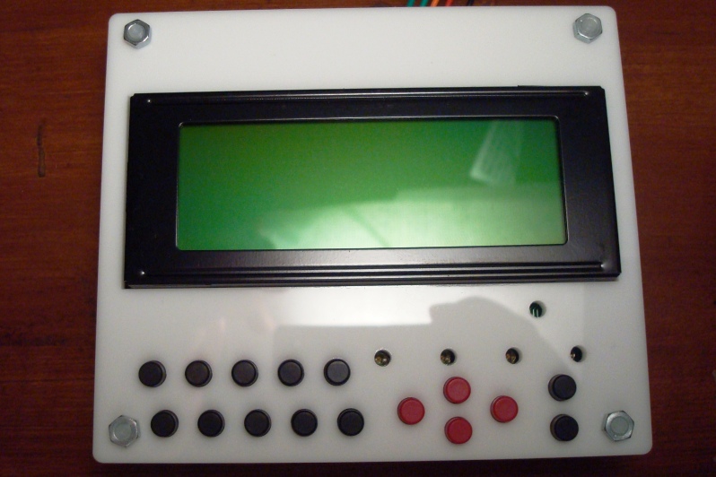
Face plates are coming out! These are white 3mm acrylic face plates made from laser cutting. I didn’t choose color since I thought I could just paint the white to any color I wanted. Well, I don’t really have a spray painting can :((

If you want to make them, just leave a message here. I’ll be posting the design file in a while.

This is the design file in Corel Draw 11 (super old version). It should export into the .svg file for laser cutting at ponoko.com with the 180mm*180mm service (cheapest) if you also have Corel Draw. Otherwise, download the .svg file. I am not sure what software to use to modify .svg if you want some changes though.

To make it, set up an account at ponoko.com and choose acrylic (3mm thickness suggested).

Contains 2 16×2 face plate, 1 20×4 face plate, and one arduino uno support.

Corel Draw file:

http://code.google.com/p/phi-panel/downloads/detail?name=phi-panel_faceplate_v3.cdr&can=2&q=

Exported .svg file:

http://code.google.com/p/phi-panel/downloads/detail?name=phi-panel_faceplate_v3.svg&can=2&q=

Suggested push buttons: EG1861-ND, caps: EG1882-ND, EG1881-ND, EG1880-ND. All these are digikey.com part numbers. These are the cheapest ones I could find.
Suggested spacers: M3 thread 8mm spacing and M3 screw: 25509K-ND, H742-ND.

Serial LCD backpack

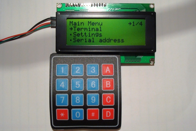
Since my success on phi-panels with integrated keypads, I’ve decided to make a serial LCD backpack as well. This backpack will support membrane matrix keypads and buzzer off board with all the same great features of the original phi-panels, just cheaper and more flexible if you want the serial backpack to make the least impact to how your project has been set up. Here it is:

At the moment, I only have 16*2 and 20*4 displays in stock but you should have no problem with 20*2 display and 40*2 displays. If in the rare occasion your display has double row pin holes, you can always solder wires between your display and the backpack.

You can set the size of the display over serial or on the on-board menu, with a 4*4 membrane matrix keypad.

This is the cheapest serial backpack out there. The I2C backpacks sold by adafruit etc. don’t have any processors on them so they will waste your arduino just as much time and FLASH space to operate as a parallel display. With the vast 24KB on-board firmware and functions, this backpack trumps any of its competitors!

I am offering these for sale on inmojo at the moment, although if you are interested in trading with me (I collect old CPUs, in the early 1990’s and earlier), I can trade with you as well. Read this post if you are interested in exchange:

Exchange!

New multi-tap keypad

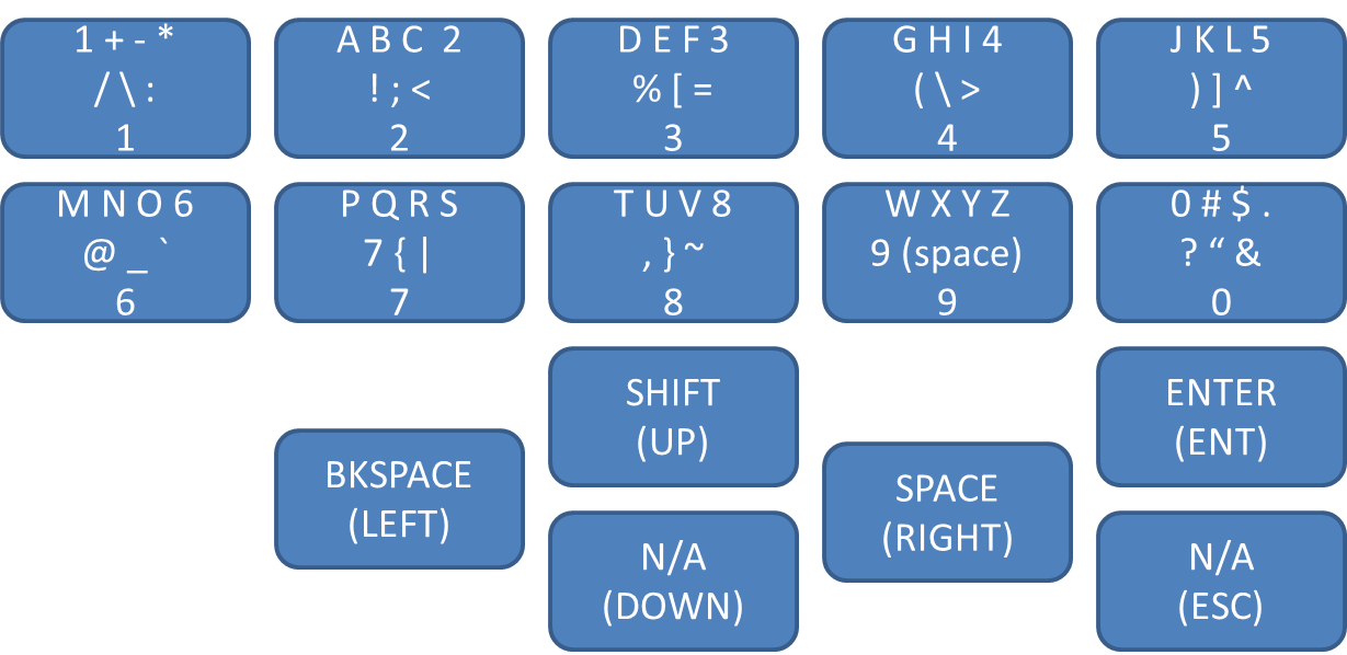
After a Phi-panel user (Daniel) has requested for more symbols on the multi-tap keyboard, I added all symbols to the keypad, why not? 🙂

Now the keypad has 7 symbols for each numeric key except for 9, with 6 symbols only. The symbols such as greater and less, brackets, parentheses, and curly braces, are all symmetrically located so if you get used to the pad, say memorized “(” is 5 presses on key “4”, then the “)” will be also 5 presses on the next key, “5”. Again all + – * / are located together on key 1.

On HD44780 displays, the ‘~’ and the ‘\’ are displayed as right arrow and the Japanese Yen (HD probably means Hitachi display). That’s unfortunate. Hope that would be a big deal for most of us.

New keypad:

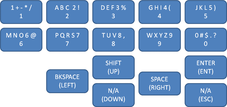
Old keypad:

To update your panel firmware, please go to the google code download page to download the firmware and follow the steps in the wiki page at the code site for updating. If you have questions, leave them here so I can answer them. Thanks.

http://code.google.com/p/phi-panel/wiki/updateFirmware

Sourcing and sinking current

Occasionally you see terms such as sourcing and sinking current and you keep wondering what they mean. So to make this clear, let’s look at sourcing and sinking current to light up LEDs:

Say you hook up an LED with a serial resistor and between an arduino output pin and gnd. If you direct the output to HIGH, you put 5V over the LED and resistor so current flows from the arduino pin to ground through the LED and resistor. In this case, you are sourcing current from the output, meaning flowing current from the pin through the LED, like turning a faucet on and flowing water out of the faucet. If you direct the output to LOW, the potential on both sides of the LED and resistor is zero so no current flows.

Say now you connect the LED and resistor between an arduino output pin and 5V. When you set the output pin to gnd, you are sinking current to the output, meaning flowing current from 5V to the output pin through the LED and resistor. It is like the arduino pin is a sink in a kitchen. Your 5V source will flow water via the LED and resistor to the sink.

Arduino pins can both source and sink when they are outputting while some other output devices such as a TLC5940, can only sink current, while others can only source current. In case only one-way conduction is allowed, you need to set up the circuit correctly to source or sink otherwise the circuit will not work or get damaged.

Rotary encoder

A rotary encoder is a digital device in the shape of a knob. You can turn it in either clockwise direction or counter-clockwise direction infinite turns, without any limit. This is what a potentiometer can’t do. In the old days most knobs are potentiometers or rotary switches, such as those on stove top, washers and dryers. Potentiometer is much easier in the concept to sense than a rotary encoder so here we discuss how to sense a digital rotary encoder.

How does it work?

A simple rotary encoder has two channels or switches. If you turn the encoder’s shaft, the two switches will open and close repeatedly much like two tactile buttons. Depending on the direction of the rotation, the sequence of the open and close will be different. Say we have two channels A and B that open and close as we turn the encoder and if we turn the encoder clockwise, we will see:

A open->B open->A close->B close

If we turn counter clockwise, we see:

B open->A open->B close->A close

So to tell which way the encoder is turning, we just need to tell which sequence occurs. There are many ways to tell which sequence occurs but I will focus on the easiest way, which is also efficient enough.

First, you combine the status of the switches A and B into a 2-bit binary number, A being the low bit and B being the high bit. Let’s define open as 1, and close as 0. Here is how to combine the status bits:

stat=(digitalRead(EncoderChnB)*2) + digitalRead(EncoderChnA);

When both channels are closed, we get 0. When both are open, we get 3. When only a is open, we get 1. When only b is open, we get 2.

Now we can translate the sequences into numbers:

A open->B open->A close->B close ==>> 1,3,2,0

B open->A open->B close->A close ==>> 2,3,1,0

Note that in the first sequence when B opens after A opens, they are both open, so that corresponds to 3.

Now we can make an array to store both sequences with a pointer:

byte stat_seq[]={0,1,3,2,0,1,3,2,0};

byte stat_seq_ptr=4;

The pointer initially points to a status of both switches closes, which is a detent position for the encoder. You turn your encoder and it clicks into detent positions. If your detent position is when both switches are open, you may use {3,2,0,1,3,2,0,1,3} instead.

Now, every time you read the two channels, you compare the stat with the array element before and after the current pointer’s position. If the stat represent the array element after the current pointer, move the pointer there, same for the other way around. When the array pointer hits the left end of the array, with a 0, you have completed one CCW turn, report this turn and reset the pointer to the middle, 4. Same for CW turn when the pointer reaches the right end of the array.

This should be easier to understand than other ways of tracking the encoder and is much more robust. Here is the complete code:

The function returns the number of CW or CCW turns stored in its buffer. Every time you call it to ask number of CW turns, it returns the turns and decrements its internal count by one. All you need to do is to keep calling this function every loop by supplying which direction you want to read back. If the read back is greater than zero, a turn is made by the user. You can decide what to do, maybe advance in a menu. If the return is zero, there is no turn in that direction, you need to do nothing. The green section is sensing the encoder and the blue section is responding the the caller.

byte read_encoder(byte direction) // 1 for asking CW counts, -1 for asking CCW counts. Returns counts and decrements the counts till 0.
{
  static byte stat_seq[]={3,2,0,1,3,2,0,1,3}; // For always on switches use {0,1,3,2,0,1,3,2,0};
  static byte stat_seq_ptr=4;
  static byte cw_counter=0;
  static byte ccw_counter=0;

  byte stat_int=(digitalRead(EncoderChnB)<<1) | digitalRead(EncoderChnA);
  if (stat_int==stat_seq[stat_seq_ptr+1])
  {
    stat_seq_ptr++;
    if (stat_seq_ptr==8)
    {
      stat_seq_ptr=4;
      cw_counter++;
    }
  }
  else if (stat_int==stat_seq[stat_seq_ptr-1])
  {
    stat_seq_ptr–;
    if (stat_seq_ptr==0)
    {
      stat_seq_ptr=4;
      ccw_counter++;
    }
  }
if (direction==1)
  {
    if (cw_counter>0)
    {
      cw_counter–;
      return cw_counter+1;
    }
    else return 0;
  }

  else if (direction==255)
  {
    if (ccw_counter>0)
    {
      ccw_counter–;
      return ccw_counter+1;
    }
    else return 0;
  }

  else return 0;
}

How to calculate current-limiting resistor for LEDs

Here is typically how you calculate the “current-limiting resistor” for an LED.

You will need to know ahead of time:

1) Supply voltage Vdd, in case of the typical 5V arduino boards, Vdd=5V

2) Typical forward bias voltage of the LED Vfb, read the spec sheet. My personal experience is that more powerful LEDs have higher value of Vfb.
Take this one for example:

http://dipmicro.com/store/LED5G

A range of 3.0 to 3.6V is given. I would try to use the average of 3.3V. Some other spec sheets give typical values and you will use that value.

3) Current rating i_m. The above LED is said to have 20mA current rating. It’s the maximal sustained current you want it to have. Again some other spec sheets give you current at typical forward bias voltage and you can use that value.

Now to calculate the current-limiting resistor, just do this:

Vdd=Vfb+Vr, where Vr is the voltage dropped on the current-limiting resistor. So Vr=i_m*R. Where i_m is the LED current rating.

So R=(Vdd-Vfb)/i_m

For the above LED, R=(5V-3.3V)/0.02A=85 ohm. That is when you are pushing a little bit. Plus, arduino pins can only supply 20mA and the entire ATMEGA chip can supply 200mA. So to be safe, I would use a 150 ohm resistor. Then the LED will be less bright. If you use the LED for lighting purpose, its brightness is relevant to you. But you use it as an indicator instead of illumination, make it not that bright by using larger resistors.

Typically, if an LED is passing 1mA of current, you can see it in the dark, or straight on in a room but hard to see from sideways. If you run 20mA on an LED, it hurts your eyes to stare at it.

The following is taken in a dark bedroom. I believe only 3 LEDs were on together, passing around 6mA each only 🙂

Phi_morse library is rolled out

Now if you want Morse code functions and can’t do it yourself, you can just download this library and call morse_out(“HELLO”);

Check out the library page:

Phi_morse library page

Phi_super_font available

After the success with Phi_big_font, I’ve created a Phi_super_font to use on 20X4 displays. The font is 20 times the size of standard font on character LCDs. Check out its library page! I’m in the process to add some cosmetic feature but the default options are already good enough to distribute 🙂